
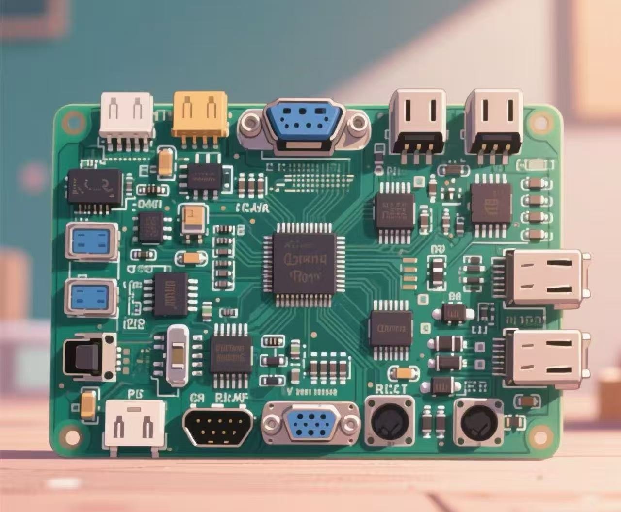
PCBA Socket Board
The PCBA Socket Board (Printed Circuit Board Assembly Socket Board) is a printed circuit board assembly integrated with various interface components. Its core function is to provide connection and transmission channels for signals, data, and power in equipment. As a key component for electronic devices to interact with external modules, peripherals, or systems, it is widely used in industrial control, consumer electronics, communication equipment, and other fields.
Get a Quote
常见的插座类型
•工业通用接口:DB9(串口)、RJ45(以太网口)、接线端子(用于电源/信号布线)和航空插头(防振动和防尘,适用于恶劣的工业环境)。
•通用电子接口:USB Type-A/C、HDMI、DVI(显示接口)、SATA(存储接口)和GPIO(通用输入/输出)接口。
主要特点
• 稳定性:为工业场景设计的插座板通常采用抗氧化的镀金触点和加固的插座外壳。这提高了抗振动性、高低温耐受性(常见范围是-40℃至85℃)和电磁干扰抗性,使它们能够适应复杂的工况条件。
•可靠性:插座与印刷电路板(PCB)之间的焊接大多使用波峰焊或回流焊工艺,以确保牢固连接并减少长期使用期间接触不良的风险。
•兼容性:接口设计符合国际标准(如USB 3.0、以太网IEEE 802.3),以确保与不同品牌和型号的外部设备兼容。
Technical Data of PCBA Socket Board
1. Overview of PCBA Socket Board
PCBA (Printed Circuit Board Assembly) refers to printed circuit board assembly, and the Socket Board is a crucial component of PCBA. Equipped with various types of sockets, the Socket Board is used to connect other electronic components, modules, or devices, playing a key role in electrical connection and physical support. It acts like a bridge, organically integrating different electronic components to ensure smooth signal transmission while providing a stable working environment for these components.
In terms of structure, a Socket Board is usually based on a printed circuit board, with sockets installed on its surface or inside according to a specific design layout. These sockets come in a wide variety of types, including IC sockets for connecting integrated circuit chips, board-to-board sockets for connecting other circuit boards, and through-hole sockets for connecting the pins of electronic components. Sockets of different types vary in size, number of pins, electrical performance, and mechanical characteristics to meet various application requirements. For example, in a computer motherboard, the CPU socket is used to install the central processing unit, and the memory socket is used to insert the memory module. The precise design and high-quality manufacturing of these sockets directly affect the performance and stability of the computer.
2. Common Types and Characteristics of Sockets on Socket Board
2.1 IC Sockets
IC sockets are specifically designed for installing integrated circuit chips, providing electrical connection and physical protection for the chips. They have distinct characteristics, with easy insertion and removal being a major advantage. This allows for easy chip replacement during chip debugging, maintenance, or upgrading without complex soldering operations, greatly improving work efficiency. For instance, during the research and development of electronic products, engineers may need to frequently replace chips of different models to test performance, and the convenient plug-and-play feature of IC sockets becomes particularly important. Meanwhile, IC sockets can effectively avoid potential thermal damage to chips during soldering. The high temperature generated during soldering may affect the precision circuits inside the chip, but this risk can be avoided by using IC sockets. Common IC sockets come in two packaging forms: DIP (Dual In-line Package) and SMT (Surface Mount Technology). The pins of DIP IC sockets are inserted into the through-holes of the circuit board and fixed by soldering, offering high mechanical strength and stability; SMT IC sockets are directly mounted on the surface of the circuit board, occupying less space and being suitable for high-density assembly requirements.
2.2 Board-to-Board Sockets
Board-to-board sockets are used to connect two printed circuit boards and are widely applied in electronic products that require modular design. They feature high connection reliability, ensuring stable signal transmission between the two circuit boards in a complex electrical environment. Taking smartphones as an example, the connection between the main board and modules such as the display screen and camera is usually achieved using board-to-board sockets. These sockets have various pin pitches, ranging from larger pitches suitable for connections with a small number of pins and low space requirements to extremely small pitches meeting the needs of high-density and high-performance application scenarios, such as the connection between high-end server motherboards and expansion cards. In addition, board-to-board sockets also have multiple connection methods, including vertical connection, horizontal connection, and right-angle connection, which can be flexibly selected according to the internal structure and spatial layout of the product, greatly enhancing design flexibility.
2.3 Through-Hole Sockets
Through-hole sockets are used to connect electronic components with pins, such as resistors, capacitors, and inductors. Their advantage lies in the ability to withstand large currents and power, making them suitable for occasions with high electrical performance requirements. In some power electronic devices, such as power modules, it is necessary to connect high-power inductors and capacitors through through-hole sockets to ensure the stable operation of the device. The pins of through-hole sockets are inserted into the through-holes of the circuit board and fixed by soldering. This connection method provides good mechanical stability and electrical connection performance. At the same time, through-hole sockets have a certain adaptability to the thickness of the circuit board, and sockets of appropriate specifications can be selected according to actual needs to ensure good compatibility with circuit boards of different thicknesses.
3. Design Key Points of Socket Board
3.1 Electrical Performance Design
3.1.1 Signal Integrity
In the case of high-frequency signal transmission, signal integrity is of crucial importance. The wiring design of the Socket Board should minimize impedance discontinuities in the signal transmission path to avoid signal reflection and crosstalk. For example, reasonably control the length and width of the lines to ensure that the characteristic impedance of the signal transmission path remains constant. Common characteristic impedance values are 50Ω and 75Ω. For high-speed differential signals, it is also necessary to ensure the length matching of the differential pairs, with the error controlled within a very small range to ensure the correct transmission and reception of signals.
3.1.2 Power Distribution
Providing a stable and clean power supply for various components connected to the Socket Board is a key aspect of the design. It is necessary to reasonably plan the power layer and ground layer to reduce the interference of power noise on signals. By setting decoupling capacitors, high-frequency noise on the power line is filtered out, ensuring a stable DC power supply for components such as chips. Meanwhile, according to the power consumption requirements of the components, the width of the power line should be reasonably designed to meet the requirements of large current transmission and prevent overheating of the power line or excessive voltage drop.
3.2 Mechanical Design
3.2.1 Socket Layout
The layout of sockets should fully consider the convenience of component installation and maintenance. Avoid overcrowding between sockets to ensure no mutual interference during component insertion and removal. For example, when designing a computer motherboard, the layout of memory sockets, PCI slots, etc., should be reasonable to facilitate users to install and replace hardware. At the same time, heat dissipation requirements should be taken into account, and components with large heat generation should not be placed too close to temperature-sensitive sockets.
3.2.2 Circuit Board Size and Shape
Determine the size and shape of the Socket Board according to the actual application scenario and the overall structure of the product. Ensure that it can perfectly fit into the product's housing or other installation spaces. In some miniaturized electronic products, such as smart watches, the Socket Board needs to be designed to be very compact to adapt to the narrow internal space. At the same time, the layout of the sockets should be reasonable to avoid affecting signal transmission and component installation.
3.3 Thermal Design
With the continuous increase in the power of electronic devices, heat dissipation has become an increasingly prominent issue. The thermal design of the Socket Board aims to ensure that the connected components operate within the normal working temperature range. For components with large heat generation, such as high-performance processors, the Socket Board can use heat sinks or thermal conductive materials for auxiliary heat dissipation. For example, in server motherboards, large heat sinks are usually installed around the CPU socket to quickly conduct the heat generated by the chip through the Socket Board, ensuring the stable operation of the CPU. In addition, reasonably designing the heat dissipation path of the circuit board, such as adding heat dissipation holes and optimizing the distribution of copper foil, can also effectively improve heat dissipation efficiency.
4. Manufacturing and Assembly Process of Socket Board
4.1 Printed Circuit Board Manufacturing
4.1.1 Substrate Selection
Select appropriate substrate materials according to the application scenario and performance requirements of the Socket Board. A common substrate material is FR-4 (glass fiber epoxy resin), which has good electrical and mechanical properties and is suitable for most general applications. For high-frequency applications, materials with low dielectric constants such as polytetrafluoroethylene (PTFE) may be selected to reduce signal transmission loss.
4.1.2 Circuit Etching
Through processes such as photolithography and etching, precise circuit patterns are fabricated on the substrate. This process requires strict control of process parameters to ensure that the width, spacing, etc., of the circuits meet the design requirements. High-precision circuit etching is crucial for ensuring the electrical performance of the Socket Board, especially in high-density wiring scenarios, where any slight circuit deviation may lead to signal transmission problems.
4.2 Socket Installation
4.2.1 Through-Hole Technology (THT)
For some sockets that need to withstand large mechanical stress or current, such as power sockets, the through-hole insertion process is usually adopted. Insert the pins of the socket into the through-holes of the circuit board, and then solder and fix them on the other side of the circuit board. This process has high mechanical strength and stability, but the production efficiency is relatively low, and large through-holes need to be reserved on the circuit board, which is not conducive to improving the integration of the circuit board.
4.2.2 Surface Mount Technology (SMT)
The SMT process is widely used in the manufacturing of modern Socket Boards. Surface-mount sockets are directly mounted on the surface of the circuit board, and the sockets are soldered to the circuit board through the reflow soldering process. The SMT process has the advantages of high production efficiency, small space occupation, and suitability for large-scale automated production, which can meet the miniaturization and high-density assembly requirements of electronic products. However, for some sockets with extremely high soldering quality requirements, manual inspection and touch-up soldering may be required after reflow soldering to ensure soldering reliability.
4.3 Quality Inspection
4.3.1 Visual Inspection
Inspect the appearance of the Socket Board through manual inspection or automated optical inspection (AOI) equipment, including checking whether the installation position of the sockets is correct, whether the solder joints are full, and whether there are defects such as cold soldering and short circuits. AOI equipment can quickly and accurately detect various defects on the surface of the circuit board, greatly improving inspection efficiency and accuracy.
4.3.2 Electrical Performance Testing
Use professional testing equipment to conduct a comprehensive test on the electrical performance of the Socket Board. This includes signal transmission performance testing to check whether the signals are transmitted normally in the sockets and circuit board circuits, and whether there are problems such as signal attenuation and reflection; power integrity testing to check whether the voltage of the power line is stable and whether the current meets the design requirements. Only through strict quality inspection can the stable and reliable operation of the Socket Board in practical applications be ensured.
5. Application Cases
5.1 Computer Field
In computer motherboards, the Socket Board plays a core role. The CPU socket is used to install the central processing unit, and its performance directly affects the computing speed of the computer. Taking Intel's LGA1700 socket as an example, it adopts a brand-new design, which can better match the 12th-generation and subsequent Core processors, providing higher performance and stability. The memory socket is used to insert the memory module, and memory sockets of different specifications support memory modules of different types and capacities, meeting the user's demand for computer memory expansion. In addition, there are various PCI slots on the motherboard for connecting expansion cards such as graphics cards, network cards, and sound cards. Through the Socket Board, efficient communication and collaborative work between various components of the computer are realized.
5.2 Communication Equipment
In 5G base station equipment, the Socket Board is used to connect various radio frequency modules, baseband processing modules, etc. For example, board-to-board sockets closely connect the radio remote unit (RRU) and baseband unit (BBU) of the base station to ensure high-speed and stable signal transmission. Since 5G communication has extremely high requirements for signal transmission rate and stability, the electrical performance and reliability of the Socket Board must meet very high standards. At the same time, in the compact space of the base station equipment, the mechanical design and layout of the Socket Board also need to be carefully optimized to meet the requirements of equipment miniaturization and efficient heat dissipation.
5.3 Industrial Control
In industrial automation control systems, the Socket Board is used to connect various sensors, actuators, and controllers. For example, in the control box of an automated production line, the Socket Board connects various actuators such as relays and contactors through through-hole sockets, and connects microcontroller chips through IC sockets to realize precise control of the production line equipment. The industrial environment is usually harsh, with problems such as high temperature, high humidity, and strong electromagnetic interference. Therefore, the Socket Board used in the industrial control field needs to have good anti-interference ability and stability to ensure the reliable operation of the system in a complex environment.
(Relevant actual pictures of Socket Boards in different application scenarios can be inserted here, such as Socket Boards on computer motherboards, Socket Boards in 5G base stations, and Socket Boards in industrial control boxes. Since direct insertion is not possible, you can add the corresponding pictures during typesetting according to the actual situation.)
In conclusion, as a key connection component in electronic devices, the PCBA Socket Board plays a vital role in the performance, reliability, and miniaturization development of electronic devices through its design, manufacturing, and application. With the continuous advancement of electronic technology, the Socket Board will also continue to innovate and develop to meet the growing diverse application needs.


