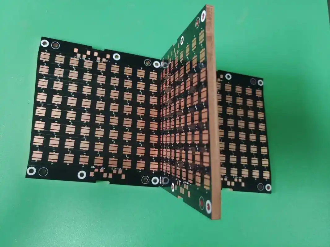
Metal PCB
Select 6061 aluminum alloy (conventional thickness of 1.0 - 3.0mm) or oxygen - free copper (for high - end scenarios). Cut it to the designed size (such as 500mm×400mm) using a CNC cutting machine, with the error controlled within ±0.1mm. After cutting, sand the surface with 120# sandpaper to remove the oxide layer and burrs (burr height ≤ 3μm). Then, clean it by ultrasonic cleaning (40℃ alkaline cleaning agent) for 15 minutes to remove oil stains. Finally, conduct chemical passivation treatment (immerse in a chromate solution for 5 minutes) to form a 50nm passivation film on the metal surface, enhancing the bonding force with the insulating dielectric layer.
Get a Quote
I. Metal Substrate Cutting and Surface Treatment
Select 6061 aluminum alloy (conventional thickness of 1.0 - 3.0mm) or oxygen - free copper (for high - end scenarios). Cut it to the designed size (such as 500mm×400mm) using a CNC cutting machine, with the error controlled within ±0.1mm. After cutting, sand the surface with 120# sandpaper to remove the oxide layer and burrs (burr height ≤ 3μm). Then, clean it by ultrasonic cleaning (40℃ alkaline cleaning agent) for 15 minutes to remove oil stains. Finally, conduct chemical passivation treatment (immerse in a chromate solution for 5 minutes) to form a 50nm passivation film on the metal surface, enhancing the bonding force with the insulating dielectric layer.
II. Preparation of Double - sided Insulating Dielectric Layer: Ensuring Insulation and Heat Dissipation (Procedures 3 - 4)
- Double - sided Synchronous Coating of Dielectric LayerAdopt the "scraper synchronous coating" process to simultaneously coat high - thermal - conductivity insulating resin (containing 60% alumina filler, thermal conductivity ≥ 3W/(m・K)) on both sides of the metal substrate. Control the coating thickness within 50 - 80μm (error ±3μm). Immediately after coating, send it to a hot - air oven and execute staged curing: 80℃ (30min) for pre - curing → 120℃ (40min) for semi - curing → 180℃ (60min) for complete curing, ensuring the cross - linking degree of the dielectric layer is ≥ 90% and the breakdown voltage is ≥ 2.5kV/mm.
- Dielectric Layer Quality InspectionUse a "pin - disk - type insulation tester" to detect the insulation of the double - sided dielectric layer (insulation resistance ≥ 10¹²Ω), sampling 20 points per square meter. Scan the whole board with a laser thickness gauge and record the thickness difference between the two sides (required to be ≤ 5μm). For local bubbles or pinholes (diameter ≥ 50μm), use the "resin re - coating + local curing" method for repair. After repair, re - test the insulation.
III. Double - sided Copper Foil Lamination and Circuit Manufacturing: Building Two - way Conductive Layers (Procedures 5 - 7)
- Double - sided Copper Foil Hot - pressing LaminationSelect 1OZ (35μm) electrolytic copper foil and laminate it simultaneously on both sides of the dielectric layer through a double - station hot - press: at a temperature of 160℃, a pressure of 20kg/cm², and a holding time of 30min. Before hot - pressing, apply a small amount of coupling agent (silane - based) between the copper foil and the dielectric layer to enhance the bonding force (required peel strength ≥ 1.5kg/cm). After lamination, sample and test with a tensile testing machine, and the non - qualification rate should be ≤ 0.5%.
- Double - sided Synchronous Pattern TransferAdopt the "double - sided alignment exposure" process: simultaneously coat photosensitive film (thickness of 15μm) on the double - sided copper foil. Ensure the alignment of double - sided patterns through an optical alignment system (positioning accuracy of ±2μm). Expose simultaneously with a UV exposure machine (energy of 100mJ/cm²), develop by soaking in a developing solution (1.0% sodium carbonate solution) to expose the copper foil to be etched. After development, check for double - sided pattern misalignment (required to be ≤ 3μm) through CCD visual inspection.
- Double - sided Etching and Film StrippingPut the substrate into a double - sided spray etching machine. Use an acidic copper chloride etchant (concentration of 180g/L, temperature of 45℃). Control the double - sided etching rate at 1.2μm/min. Ensure the double - sided line - width deviation is ≤ ±3μm through "etching time - difference compensation" (adjust ±5 seconds according to the thickness deviation of the double - sided copper foil). After etching, strip the film simultaneously with a 5% sodium hydroxide solution. After film stripping, conduct AOI inspection, focusing on checking for open - circuits, short - circuits, and edge burrs (≤ 5μm).
IV. Inter - layer Interconnection and Post - treatment: Ensuring Overall Reliability (Procedures 8 - 10)
- Double - sided Positioning DrillingUse an "X - ray positioning drilling machine" to position through the reference holes at the edge of the substrate and simultaneously process the through - holes (aperture of 0.3 - 0.5mm) for double - sided interconnection. The hole - position deviation is ±0.02mm. After drilling, blow out the metal debris in the holes with compressed air (0.5MPa) to avoid short - circuits. For small holes with an aperture ≤ 0.3mm, adopt the "laser pre - drilling + mechanical fine - drilling" composite process to reduce the risk of drill breakage.
- Via Metallization and Surface TreatmentFirst, conduct electroless copper plating (copper - plating thickness of 0.8 - 1μm) to ensure the conductivity of the hole wall. Then, thicken the copper layer on the hole wall to 25μm through vertical electro - plating, and at the same time, electro - plate and thicken the double - sided circuit surface by 5μm. For surface treatment, use "double - sided synchronous gold - plating" (2μm gold layer, 5μm nickel layer) or "tin - spraying". After treatment, verify the weather resistance through a salt - spray test (no corrosion in 48 hours). For substrates used in new - energy vehicles, additionally conduct "edge sealing" (coat silicone rubber) to enhance moisture resistance.
- Shape Processing and Finished - product InspectionCut the shape of the substrate with a CNC milling machine at a cutting speed of 50mm/min to avoid burrs on the metal base. After cutting, conduct a "double - sided conductivity test" (use a flying - probe tester to detect the conductivity of all circuits and through - holes), a "thermal resistance test" (measure the temperature rise under a 10W power through an infrared thermal imager, required to be ≤ 30K). Finally, sample for a "temperature - cycling test" (-40℃~125℃, 500 times), and it is qualified if there is no delamination or hole - copper fracture.


